Audio Oscillator Project
Lately I've been loading some of the earliest SolderSmoke episodes into my mp3 player. I've really been enjoying them. In the very first, Bill mentioned that he was warming up the soldering iron because he just felt like making something and melting some solder. With that in mind this weekend, I decided that I was just going to build something.
So I opened up EMRFD and turned to chapter 7, which I knew had some simple projects like oscillators, rf probes, watt meters, etc. I came down on the simple one frequency audio oscillator (page 7.13, Fig 7.24) that they wrote was useful for testing audio sections of a radio. (Keeps you from having to whistle in the the mic.) Since I am aspiring to one day building a reciever from scratch, and maybe even an SSB transmitter I figured I'd give it a shot.
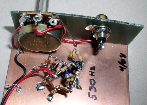
I've never built anything in the "true" ugly style with a plain groundplane. I also decided to begin the project with the end in mind, connectors and controls. In the case it was pretty simple. A pot for output level and an output jack of some kind. So, I also added the flange at the beginning. Here is a picture of what I ended up with. I think it compares to the photo in EMRFD, if I say so myself :) ).
This is actually the first sine wave oscillator I've ever successfully built. In the past I've always had to fall back on the 555 timer square wave oscillator.
Since I didn't have the capacitors used in the EMRFD version, and because they wrote that it could be built with whatever was on hand, I decided to use four of the 22nF ceramic disc capacitors from my junk box. Beyond that I didn't know how to substitute my capacitors into the design. I knew that this was a phase shift oscillator that worked by feeding an inverting amplifier with a feedback loop made of a phase shifting RC network. And that to oscillate, the network needed to shift the phase of a particular frequency an additional 180 degrees. But how did I pick resistors to select a frequency?
I found a web site that talked about this and used an equation from it. f=1/(2*pi*R*C) Being young and dumb I took the equation and rearranged it to find R and slapped my values in: R = 1/(2*pi*1200Hz*22nF). Using my trusty calculator I found that roughly R=6k Ohms. I selected 5.6 as the standard value resistor and started building. (Note if you are reading this to figure out how to substitute in your own capacitors that this did not work. You can see on the photo that I ended up with an oscillator for 530Hz, not 1200Hz that I was shooting for.)
I built the oscillator in a hour or two plugged in the battery and got nothing. No voltage (AC or DC) at the output. Bummer! I checked the DC voltages and resistances of the various nodes and nothing seemed amiss. Still no output. Well it was getting late so I slept on it.
The next day I searched the web again and struck gold. I found an oscillator design that had a small section talking about adjustment of the emitter resistance to get the least distortion. It said to adjust the resistance so it was just below the resistance that would stop oscillation. Ok, now I had something the try. My emitter resistance was 10k Ohms. I used a jumper with clips to add an 18k resistor in parallel and it worked! I played with the resistor value and ended up adding a 22k resistor in parallel for 6.8k Ohms total or so.
A sine wave.!I could hear it! Seemed a little low though.
I plugged the output into my computer's "mic in" and fired up Spectrogram and Soundcard Scope. Yep it was nice and clean with the second harmonic about 32dB down from the primary. But the primary frequency was 530Hz. Why?
On further reading it appears that I should have used the equation f=1/(2*pi*sqrt(6)*R*C) which is further down on the first site. However, that would actually make the error worse, wouldn't it? I compared schematics between EMRFD and the web site and found that EMRFD had one more capacitor in the phase shift network. I shorted out that last capacitor with a jumper and ... killed the oscillations.
So I don't know exactly what is happening, but I suspect that the two problems I've had are related.
Anyone got any ideas? I'm all ears.
UPDATE 4/25/08: I've drawn up a schematic as of the oscillator as built; Here it is:
